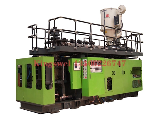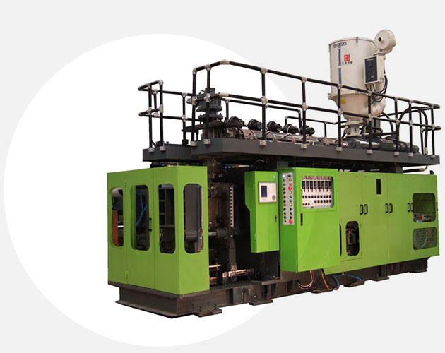
What is the mechanical principle of the automatic blow molding machine pneumatic blowing machine?
1. High-precision screw nut is used for opening mold, clamping and thimble, and the transmission precision is 0.01mm.
2. Linear guides convert traditional reciprocating sliding guidance into rolling guidance, improve positioning accuracy, reduce machine cost and save power, and maintain high precision for a long time.
3, the use of a new type of load cell, accurate control of back pressure to achieve stable precision injection molding.
4. Synchronous pulley and timing belt, simple structure, convenient installation, high transmission precision and low noise.
5. Adopt centralized lubrication and volumetric proportional distributor to ensure sufficient lubrication at every point.
Automatic blow molding machine
Anti-reverse ring (over the apron) --- As the name suggests, the role of the anti-reverse ring is to stop the inverse. It is a part that prevents the plastic melt from leaking back during injection.
Blowing machine die
The die is the transition between the coupling barrel and the mold.
Gas needle
The gas needle is a part that connects the die and the barrel. It only acts as a bulge during the plasticizing and blowing process of the plastic.
Feeding hopper
The hopper is a component for storing plastic raw materials, and some are provided with a heating and blowing device to form a drying hopper on the hopper.
Pneumatic blowing bottle electrical control principle:
Servo system: An automatic control system that allows an output control amount such as the position, orientation, and state of an object to follow an arbitrary change of the input target (or a given value). The main task of the servo is to control the power, amplify, transform and adjust the power according to the requirements of the control command, so that the torque, speed and position control of the drive device are very flexible and convenient.
Mode-locked servo motor
The working principle of the servo motor:
The servo motor is a typical closed-loop feedback system. The reduction gear set is driven by a motor. The terminal (output) drives a linear proportional potentiometer for position detection. The potentiometer converts the corner coordinate into a proportional voltage feedback to the control circuit board. The control circuit board compares it with the input control pulse signal to generate a correction pulse, and drives the motor to rotate in the forward or reverse direction, so that the output position of the gear set coincides with the expected value, so that the correction pulse tends to be zero, thereby achieving the servo The purpose of precise motor positioning.
Servo motor control:
The standard servo motor has three control lines: power, ground and control. The power and ground lines are used to provide the internal motor and the energy required to control the line. The voltage is usually between 4V and 6V. The power supply should be isolated from the power supply of the processing system as much as possible (because the servo motor generates noise). Even small servo motors are pulled low during heavy loads
The voltage of the amplifier, so the proportion of the power supply to the entire system must be reasonable. Input a periodic forward pulse signal. The high-level time of this periodic pulse signal is usually between 1ms and 2ms, and the low-level time should be between 5ms and 20ms.
Contact: Mr. Zhu
Mobile: 13506226747
Tel: 0512-56766606
Fax: 0512-56766608
Email: wd@kingswel.com.cn
Address: No. 28 Guotai north Rd, Zhangjiagang, Jiangsu,China
Website: www.wangdaomachine.cn